Vasudhendra Badami

Author
Vasudhendra Badami

Blogs
With years spent in HR trenches, Vasudhendra is passionate about what makes organizations tick—people. Their writing dives deep into behavioral interviews, talent strategy, and employee experience.
author’s Articles

Insights & Stories by Vasudhendra Badami

Whether you're building your first team or scaling culture across regions, Vasudhendra Badami's articles offer human-first insights rooted in real practice.
Clear all
Thank you! Your submission has been received!
Oops! Something went wrong while submitting the form.
Filter
Filter

MQTT protocol - Powering Facebook messenger to IoT devices

In 2011, Lucy Zhang, Ben Davenport and Jon Perlow joined Facebook and started building the Facebook messenger. A major hurdle in their endeavor was long latency when sending a message. The method that they were using to send messages was reliable but slow. They were also able to optimize it to a certain extent. A few weeks before the launch, they explored the Messaging Queuing Telemetry Transport (MQTT) protocol. With the help of MQTT, Lucy Zhang and team were able to establish and maintain a persistent connection with the Facebook servers without reducing the battery life.

So, what is MQTT protocol?

Created in 1999 by Dr. Andy Stanford-Clark of IBM and Arlen Nipper of Arcom, MQTT is a lightweight messaging protocol on top of TCP/IP protocol. MQTT is designed for constrained devices (devices with low memory and network bandwidth) and wireless networks with varying levels of latency due to unreliable connection.

MQTT protocol is a client-server, publisher/subscriber, open, and light-weight messaging transport protocol. At the heart of MQTT is the central communication point known as MQTT broker. It is responsible for dispersing messages to rightful clients.

Each client which publishes a message to the MQTT broker includes the routing information, known as topic. Clients may subscribe to multiple topics and broker all the messages published matching the topic. The clients don't have to know each other to receive information; they just have to subscribe to relevant topics.

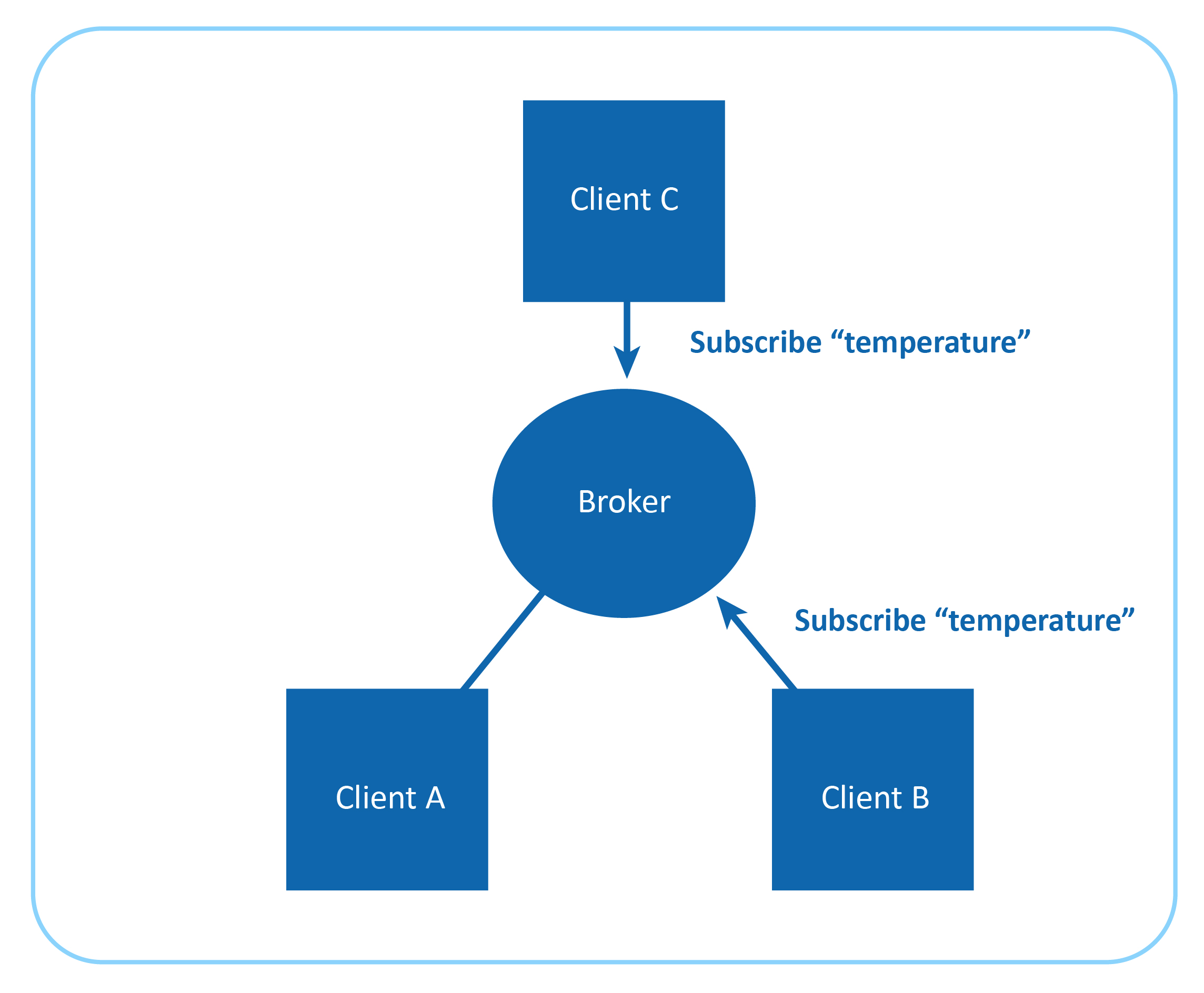
For instance, imagine a simple network of three clients, i.e A, B and C, where each is connected to a broker via a TCP connection. Client-B and Client-C subscribe to topic: temperature.

MQTT Protocol architecture

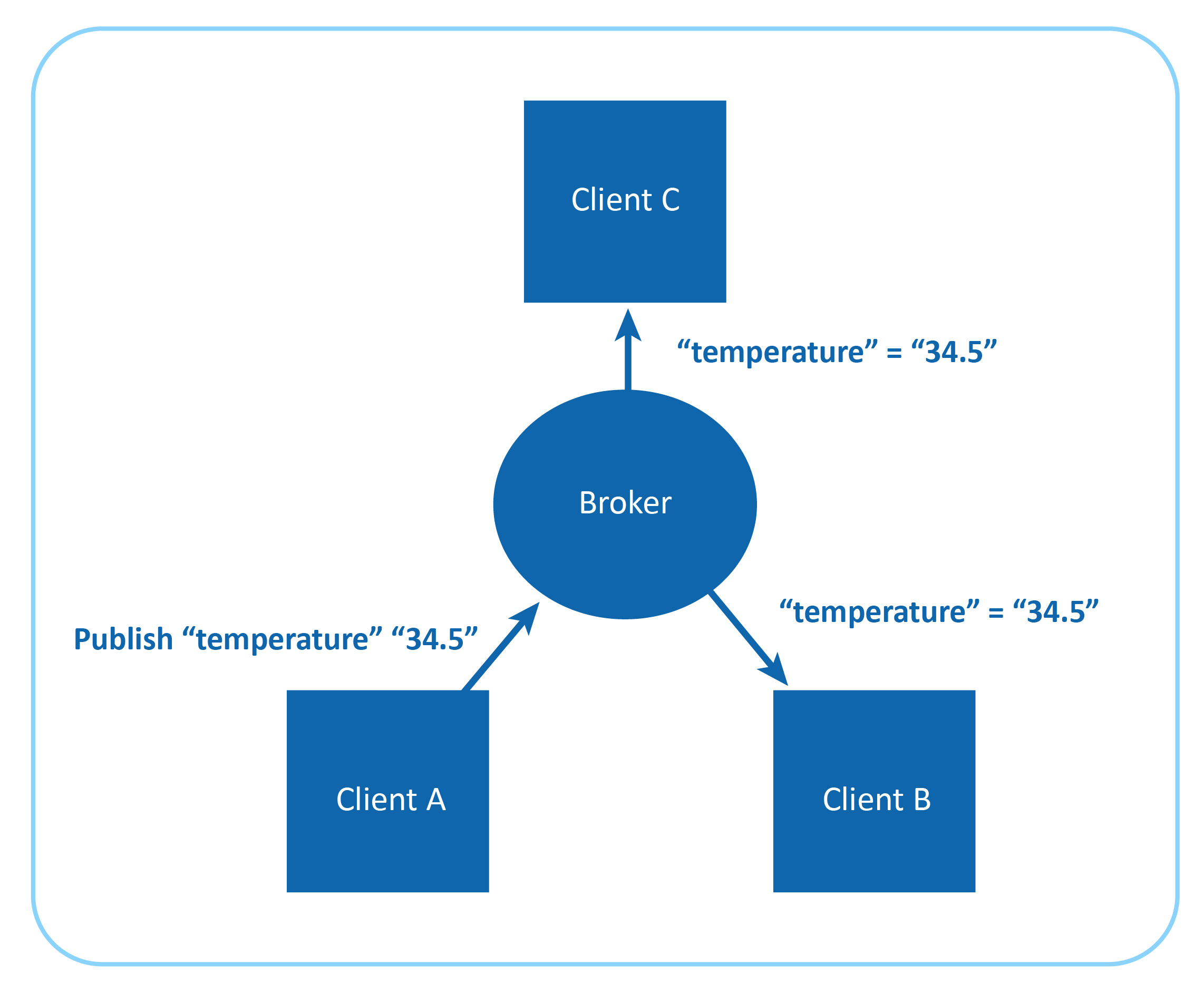
Client-A publishes 34.5 for topic temperature. The broker identifies this and forwards this message to all the subscribers, which in this case are Client-B and Client-C.

Working of MQTT protocol

The publisher-subscriber architecture of MQTT makes it a highly scalable solution, without creating dependencies between data producers and consumers.

Message format of MQTT protocol

All the messages of MQTT have a small code footprint, hence it is popular as a lightweight messaging protocol. Each MQTT message consists of the following:

  • Fixed header (2 bytes)
  • Optional variable header
  • Message payload (<= 256MB)
  • Quality of Service (QoS) level

MQTT supports one-to-one, one-to-many, and many-to-many communication.

By lowering the amount of data transmitted, MQTT makes itself a perfect protocol for constrained IoT devices.

Message payloads are encoded in binary. In an open network where the recipient is from a different manufacturer will face issues decoding it as there is no information of how message payload is encoded.

Quality of Service (QoS) level for MQTT protocol

The quality of service levels determines how the content is managed. MQTT uses three different QoS levels. It is important to choose the right QoS level for every message because it determines how the client and server communicate to deliver the message. The QoS levels of MQTT are as follows:

  • QoS 0 : Messages delivered per the best efforts of the operating environment, but message loss can occur
  • QoS 1 : Messages delivery assured but duplicates can be created
  • QoS 2 : Message to deliver exactly once

MQTT provides us with an option to set the appropriate QoS level, but remember, higher the QoS, lower the performance.

Security of MQTT protocol

MQTT allows you to pass username and password as an MQTT packet. Encryption of a message across the network can be handled independently of MQTT with Secure Sockets Layer (SSL). It has a minimal authentication feature built in. Username and password are sent as clear text. To make it secure, Secure Sockets Layer (SSL)/ Transport Layer Security (TLS) must be employed, but SSL/TLS is not a lightweight protocol.

Many industry experts believe MQTT will play a major role in IoT by contributing to fields such as inventory tracking, and medical IoT..

How Fukushima nuclear disaster powered smart farming in Japan

On March 11, 2011, the most intense earthquake in Japanese history hit its north east coast — magnitude 9.0. The earthquake was so powerful that it severely damaged buildings, road, and rail infrastructure in Tokyo, which was 373 km away from the epicenter. This was an undersea megathrust earthquake.

Fifty minutes after the earthquake, tsunami waves as high as 13 meters hit the eastern part of Japan, leaving more than 15,500 dead, 6,000 injured, and 2,500 people missing. The tsunami struck so hard that it resulted in a Level-7 nuclear disaster in Fukushima (in Japanese, Fukushima means Fortune Island); it is the second nuclear disaster in the history of mankind which was given level-7 criticality after the Chernobyl disaster in 1986.

Fukushima had six separate boiling water reactors maintained by Tokyo Electric Power Company (TEPCO). Due to the powerful earthquake and tsunami, the nuclear power plant in Fukushima was subjected to serious structural damage. This resulted in hydrogen-air explosion on top of each nuclear reactor, releasing huge amounts of radioactive particles including Iodine-131, Caesium-134/137, Tellurium-129m, and Strontium 90 into the atmosphere. These radioactive particles contaminated air, soil, and water in and around Fukushima.

Unfortunately, Fukushima was one of the most agriculturally important regions in Japan. There are close to two million farmers in Japan, of which 70,000 are in Fukushima. The farmers of Fukushima had to deal with radioactive contamination of their soil, crops, livestock, and the marine ecosystem in addition to the tragedy caused by the tsunami. Due to radioactive contamination everywhere, the government of Japan imposed restrictions on the growing and selling of crops, dairy products, and seafood.

Now, Japan needed to increase its production to make up for the agricultural loss in Fukushima and, very importantly, it needed food products without radioactive contaminants. If this is not achieved, Japan would head toward a food crisis.

In Kameoka (a satellite town to the west of the Japanese city of Kyoto), the Japanese agriculture technology company SPREAD had started working on a smart farming system on barren land. SPREAD built a vegetable factory in a 2868.22 m2-area.

Inside the doors of this warehouse-like agriculture complex, SPREAD uses vertical farming system.

SPREAD vegetable factory grew lettuce in a soil-less and sunless ecosystem.

SPREAD vertical farming system.
Inside SPREAD vegetable factory

In an interview with CNN on September 19, 2016, Shinji Inada, the president of SPREAD, said, "The turning point was the incident in 2011 at the Fukushima nuclear facility. After what happened there, people became more aware of the importance of safe food and it kind of turned the tables for us."

Here a sophisticated form of hydroculture known as the Hydroponics method is used, where plants are grown in an aqueous solution of mineral nutrients with water as a solvent. In this method, terrestrial plants are grown with roots exposed to a mineral nutrient solution.

Hydroponics method of farming

Since this is an indoor farm, LED lights on top of each shelf provide adequate light for photosynthesis and the growth of lettuce.

indoor farm with LED lights on top
Indoor vertical farm with LED lights on top

At this vegetable factory, human involvement is restricted to sowing the seeds; later, everything till the harvest is taken care of by robots and sensors.

With the help of modern sensor technology, the following factors are measured:

  • Lighting
  • Level of nutrients in the mineral solvent
  • Humidity level inside the setup
  • Temperature level inside the setup
  • Level of CO2

To maintain these factors at the optimal level, robots are installed which take corrective measures.

The lettuce is grown in a highly controlled environment at this facility. As a result of not using any fertilizer, the lettuce grown at this agriculture facility is richer in beta-carotene (an antioxidant) than farm-grown lettuce.

The setup has stacker cranes which carry the stacks to the robots for harvesting after they have reached maturity. It takes 40 days for a lettuce head to be ready for harvest, whereas it takes two months for farm-grown lettuce. After the harvest, the lettuces are moved to the packaging section without any outside intervention. There are either retail or packaging boxes wholesale used for that purpose. The SPREAD’s facility at Kameoka has an output capacity of 21,000 lettuces per day.

This innovative move by SPREAD is not only providing vegetables free from radioactive contamination but also contributing to the ecology to a great extent. Here is how:

Water Recycling

Water used for cultivation of lettuce in the vegetable factory is reused after filtration and purification. At this facility, 98% of water is recycled, and it significantly reduces the water consumption—a mere 0.83 liters is used to grow one head of lettuce.

Water recycling in SPREAD vegetable factory
Water recycling system at SPREAD vegetable factory

Zero damage due to pesticides

Since this vegetable factory uses the hydroponics method to cultivate lettuce, pesticides are not required during the cultivation lifecycle. Hence, soil and water contamination is prevented and the balance of microbes and insects in ecosystem is preserved.

Reduction in energy consumption

SPREAD has developed specialized LED lights and an air conditioning system to be used at their vegetable factory, reducing the energy consumption by 30%.

SPREAD is currently working on a second vegetable factory at Keihanna, with an output capacity of 30,000 heads of lettuce per day with 86.7% reduction in water usage.

7 open source IoT operating systems that are democratizing the IoT space

The power of Open Source is the power of the people. The people rule

– Philippe Kahn (the creator of world’s first camera phone)

The open source movement, which started in 1998 as a niche, went on to become mainstream after the success of projects like Linux, Ubuntu, MySQL, Apache, etc. Later, big companies like IBM, Microsoft, and Apple began adopting the open-source software development model.

Today, companies in the IoT space like Samsung, Google, Huawei, and ARM are embracing open source by opening their hardware and software projects to the developer community and inviting contributions to build robust and reliable technology.

Here are 7 open-source operating systems for IoT devices that power a wide range of smart devices, from wearables to autonomous vehicles.

Note: All listed operating systems have two key traits:

  • Low memory footprint
  • High power efficiency

Brillo

Google's Android-based OS for embedded devices, capable of running on devices with at least 128MB ROM and 32MB RAM.

Supported communication protocols:

  • Wi-Fi
  • Bluetooth
  • Thread

Brillo supports secure boot, OTA updates, and architectures including ARM, Intel, and MIPS.

Contiki

Created in 2002 by Adam Dunkels, this BSD-licensed OS includes a TCP/IP stack and multitasking support, and runs on devices with 30KB RAM/ROM.

Supported hardware includes:

  • TI CC2538
  • nRF52832
  • TI MSP430x
  • Atmel AVR, Atmega128rfa1

RIOT

Developed by a German-French university consortium, RIOT is a real-time OS using a microkernel. It runs on 8-32bit microcontrollers.

Supported protocols:

  • 802.15.4 Zigbee
  • 6LoWPAN
  • ICMP6, IPv6, RPL, CoAP

Runs on devices with 1.5KB RAM and 5KB ROM; supports MSP430, ARM7, Cortex-M0/M3/M4, x86.

Huawei LiteOS

Developed by Huawei, this 10KB-size real-time OS supports auto discovery, zero configuration, and networking.

Supported protocols:

  • LTE, NB-IoT
  • Wi-Fi, 6LoWPAN

Supports multi-CPU architectures: ARM, DSP, MIPS, x86. Can integrate with Android devices and third-party systems.

Apache Mynewt

Apache-licensed real-time OS that runs on devices with 8KB RAM and 64KB ROM. The 6KB kernel supports:

  • Preemptive multithreading
  • Priority scheduling
  • Memory management
  • Watchdogs

Currently supports only Bluetooth Low Energy but future support includes Wi-Fi, Thread, Bluetooth 5.

Supported boards:

  • Arduino Zero, Zero Pro, M0 Pro
  • Arduino 101, Primo

Zephyr

A Linux Foundation project under Apache 2.0 license, launched in 2016. It uses static compilation for increased security.

Minimum memory: 8KB. Supported protocols:

  • Bluetooth, Bluetooth LE
  • Wi-Fi, 6LoWPAN
  • CoAP, NFC

Supported architectures: ARM, x86, ARC, RISC-V, NIOS-II.

Ubuntu Core

Canonical’s Snappy Ubuntu Core 16 is based on snap packages. The base image is 350MB, with all components stored as isolated images.

Supported boards:

  • Qualcomm Dragonboard
  • Samsung Artik
  • Intel Joule
  • Raspberry Pi 2 and 3

Read more: Ubuntu Core 16: Building secure and interoperable IoT ecosystems.

Open source is not just a development model, but a powerful opportunity for coders worldwide to make an impact and touch lives through collaboration and contribution.

Ubuntu Core 16: Building secure and interoperable IoT ecosystems

I have attended several IoT conferences, informal meetups, webinars, and podcasts. The most common questions during networking or Q&A sessions revolve around security and interoperability of IoT devices.

These concerns are valid, especially in light of recent Distributed Denial of Service (DDoS) attacks affecting Internet-connected devices.

To build consumer trust, companies in the IoT space—both hardware and software—are heavily investing in R&D to tackle these concerns sustainably.

In one such initiative, Canonical, the company behind Ubuntu, launched Ubuntu Core 16. Also known as Snappy, this is a minimal operating system designed for IoT devices. At its core are secure, remotely upgradeable Linux packages called 'snaps'.

Device Security

Ubuntu Core 16 secures IoT devices by delivering the entire operating system—including kernel, libraries, and applications—as snaps. The OS automatically updates to defend against new threats.

Snaps ensure security and reliability through the following features:

  • Read-only
  • Tamper-proof
  • Digitally signed
  • Stored as images

This architecture makes it very difficult to breach devices remotely without physical access.

Being transactional in nature, Ubuntu Core 16 automatically rolls back any failed updates, giving developers the freedom to innovate without compromising system stability.

The system retains multiple updates and selects the healthiest for installation. If an update fails, rollback ensures continuity.

Each Snap includes a meta/snap.yaml file, where developers can define:

  • Security requirements
  • Integration details with the system
  • Update schedules

This automates the update process, removing the need for human intervention.

Device Interoperability

Ubuntu Core 16 enables snaps to communicate and work together via:

  • Interfaces: Bridges between snaps
  • Plugs: Consumer snaps requesting services
  • Slots: Producer snaps offering services

Interfaces, plugs and slots in Ubuntu Core 16

Snaps Interfaces Example

Plug (Consumer Snap)

name: consumer_snap_name
plugs:
  db:
    interface: mysql

Slot (Producer Snap)

name: producer_snap_name
slots:
  db:
    interface: mysql

This setup enables both snaps to share a database. Additionally, snaps can share files with:

  • Other snaps from the same vendor
  • Community-maintained shared snaps using content-sharing interfaces

Additional Features of Ubuntu Core 16

Compatible with desktops, servers, and devices like Intel Joule, Qualcomm Dragonboard, Samsung Artik, Raspberry Pi2 and Pi3.

  • Keeps files compressed and signed using SquashFS blobs, avoiding file scattering across disks.
  • Compact OS with an image size of only 350 MB.
  • System and application updates use xdelta diffs—only changed code is updated.
  • Separation of kernel/device drivers and OS/snaps allows parallel development by different teams.

The term "Ubuntu" originates from Southern Africa and stands for “the belief in a universal bond of sharing that connects all humanity.” While technology can simplify and connect, it must be rooted in ethical principles.

No advanced system can safeguard humanity unless guided by sensible and humane ideologies. Building smart systems begins with building a thoughtful ecosystem of responsible people.

Arduino programming for beginners -2

In the previous article, we studied the basic structure of Arduino programming with examples. Now, let's look at a few more Arduino programming concepts:

  • if statement
  • if else statement
  • for loop
  • while loop
  • do while loop
  • pinMode
  • digitalRead
  • digitalWrite
  • analogRead
  • analogWrite

if statement

The if statement checks a condition and executes the block if true.

if (x == y) {
  // statements
}

Comparison operators:

  • == equal to
  • != not equal to
  • < less than
  • > greater than
  • <= less than or equal to
  • >= greater than or equal to

Note: = assigns value; == compares values.

if (LED == HIGH) {
  digitalWrite(LED, LOW);
}

if-else statement

The if-else structure chooses between two blocks depending on the condition.

if (LED == HIGH) {
  digitalWrite(LED, LOW);
} else {
  digitalWrite(LED, HIGH);
}

With else if:

if (x > 100) {
  // do something
} else if (x == 100) {
  // do something else
} else {
  // another option
}

for loop

Executes a block of code a specific number of times.

for (int x = 0; x < 50; x++) {
  digitalWrite(12, HIGH);
  delay(1000);
  digitalWrite(12, LOW);
  delay(1000);
}

Note: x++ is shorthand for x = x + 1

while loop

Runs as long as a condition is true.

while (i <= 200) {
  digitalWrite(12, HIGH);
  delay(1000);
  digitalWrite(12, LOW);
  delay(1000);
  i++;
}

do while loop

Executes the block at least once, then continues if the condition is true.

do {
  temperature = readSensor();
  digitalWrite(13, HIGH);
  delay(1000);
} while (temperature <= 35);

pinMode

Sets the mode of a digital pin to INPUT or OUTPUT.

pinMode(13, OUTPUT);

Note: Digital pins default to INPUT mode.

digitalRead

Reads the state (HIGH or LOW) of a digital pin.

state = digitalRead(2);

digitalWrite

Sets a digital pin HIGH or LOW.

digitalWrite(12, HIGH);
digitalWrite(13, LOW);

analogRead

Reads a value (0–1023) from an analog pin.

value = analogRead(A0);

analogWrite

Writes a PWM signal (0–255) to a PWM-enabled digital pin.

analogWrite(9, 255);

Note: Analog pins do not require pinMode configuration.

Congratulations! You’ve completed the basic level of Arduino programming. In the next article, we’ll explore working with different sensors. Until then, keep building!

Arduino programming for beginners-1

After understanding the hardware of the Arduino UNO board in the previous article, let's now get started with Arduino programming.

Arduino programs are written in the Arduino Integrated Development Environment (IDE). Arduino IDE is a special software that allows you to write sketches (programs) for different Arduino boards. The Arduino programming language is based on a simple hardware programming language called Processing, which is similar to the C language. After writing a sketch in the Arduino IDE, it should be uploaded to the Arduino board for execution.

The first step in programming the Arduino board is downloading and installing the Arduino IDE. It runs on Windows, Mac OS X, and Linux. Download the software from the official website and follow the installation instructions.

Now let’s discuss the basics of Arduino programming.

The structure of an Arduino program includes two main blocks:

  • Preparation
  • Execution
void setup() {
  // initialization statements
}

void loop() {
  // execution statements
}

The setup() function runs once when the program starts. It’s used to initialize pin modes and start serial communication. Even if there are no statements, the function must be included.

void setup() {
  pinMode(pin-number, OUTPUT); // set pin as output
  pinMode(pin-number, INPUT);  // set pin as input
}

After setup(), the loop() function runs repeatedly and contains the main program logic.

void loop() {
  digitalWrite(pin-number, HIGH); // turn ON
  delay(1000); // wait 1 second
  digitalWrite(pin-number, LOW);  // turn OFF
  delay(1000); // wait 1 second
}

Note: Arduino measures time in milliseconds.

Let’s Try Two Experiments

  • Blinking the LED
  • Fade-in and fade-out the LED

Building the breadboard circuit is just as important as writing the Arduino code.

Components Required:

  • Arduino UNO R3 - 1
  • Breadboard - 1
  • Breadboard connectors - 3
  • LED - 1
  • 1K resistor - 1

Blinking LED

Steps:

  1. Connect the Arduino to your computer via USB.
  2. Connect digital pin 13 to the positive rail of the breadboard; GND to the negative.
  3. Connect the positive rail to a terminal strip through a 1K resistor.
  4. Fix the LED below the resistor on the strip.
  5. Connect the LED's cathode to the negative rail.

Blinking LED circuit

Code Version-1:

int LED = 13;

void setup() {
  pinMode(LED, OUTPUT);
}

void loop() {
  digitalWrite(LED, HIGH);
  delay(1000);
  digitalWrite(LED, LOW);
  delay(1000);
}

Code Version-2:

void setup() {
  pinMode(13, OUTPUT);
}

void loop() {
  digitalWrite(13, HIGH);
  delay(1000);
  digitalWrite(13, LOW);
}

Arduino IDE

Fade-in and Fade-out the LED

Note: Use digital pin 9 instead of 13 in the above circuit.

Fade LED circuit

Code Version-1:

int led = 9;
int brightness = 0;
int fade = 5;

void setup() {
  pinMode(led, OUTPUT);
}

void loop() {
  analogWrite(led, brightness);
  brightness = brightness + fade;

  if (brightness <= 0 || brightness >= 255) {
    fade = -fade;
  }

  delay(30);
}

Code Version-2:

int led = 9;

void setup() {
  pinMode(led, OUTPUT);
}

void loop() {
  for (int fade = 0; fade <= 255; fade += 5) {
    analogWrite(led, fade);
    delay(30);
  }
}

Both programs use analogWrite() on a PWM-capable digital pin. PWM pins simulate analog output.

Congrats! You’ve completed level-1 of Arduino programming. In level-2, you’ll explore conditional statements, loops, and I/O operations. Continue learning here.